In this post, we will discuss the design considerations of Casting. Complex parts, which are otherwise difficult to machine, are made by the casting process using a sand mold. There are different types of casting processes.
Casting is an engineering manufacturing process that is used for mass production purposes. In casting, liquid materials or materials in the molten state are poured into a mold where it gets solidified. Mold contains a hollow cavity of the desired shape of the parts to be cast.
Almost any metal can be melted and cast. Most of the sand cast parts are made of cast iron, aluminum alloys, and brass. The size of the sand casting can be as small as 10 grams to as large as 200 x 103 kg.
Sand castings have irregular and grainy surfaces and machining is required if the part is moving with respect to some other part or structure. Cast components are stable, rigid, and strong compared to machined or forged parts.
A typical example of cast components is the machine tool bed and structure, cylinder block of the internal combustion engine, pump, and gearbox housing.
Poor shaping of a cast iron component can adversely affect its strength more than the composition of the material. Before designing casting, the designer should consult the foundryman and the pattern maker, whose cooperation is essential for a successful design.
Table of Contents
Types of Casting Processes
- Sand Casting
- Die Casting
- Investment Casting
- Centrifugal Casting
For successful casting, proper control of a large number of variables such as properties of metals or alloys casts, casting methods, and the various process parameters is required.
You may also want to see-
Design Considerations of Casting
- Always keep the stressed areas of the part in compression.
- Round all external corners.
- Wherever possible section thickness throughout should be held as uniform as compatible with overall design considerations.
- Avoid the concentration of metal at the junction.
- Avoid very thin sections.
- Short blast the parts wherever possible.
The general principles for the design of casting are as follows
Always keep the stressed areas of the part in compression
Cast iron has more compressive strength than its tensile strength. The balanced sections with equal areas in tension and compression are not suitable for cast iron components. The casting should be placed in such a way that they are subjected to compressive rather than tensile stresses as shown in the below figure 1.
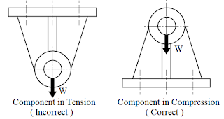 |
| Fig. 1 Always keep the stressed areas in compression. |
When tensile stresses are unavoidable, a clamping device such as a tie rod or a bearing cap as shown in figure 2 should be considered. The clamping device relieves the cast iron components from tensile stresses.
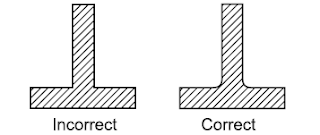
Rounding all external corners has two advantages – it increases the endurance limit of the component and reduces the formation of brittle chilled edges. When the metal in the corner cools faster than the metal adjacent to the corner, brittle chilled edges are formed due to iron carbide.
An appropriately filled radius reduces the concentration. The values of the corner radii for different section thicknesses are given in the table below.
|
Wall Thickness
(mm)
|
Inside corner radius (minimum)
(mm)
|
|
0-30
|
10
|
|
30-50
|
15
|
|
50-80
|
20
|
|
80-120
|
30
|
Wherever possible section thickness throughout should be held as uniform as compatible with overall design considerations
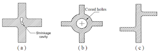 |
| Fig. 4 Concentration of metal at junctions. |
Even after the metal on the surface solidifies, the central portion still remains in the molten stage, with the result that a shrinkage cavity or blowhole may appear at the center. There are two ways to avoid the concentration of metal. One is to provide cored opening the webs and ribs, as shown in figure 4 (b).
